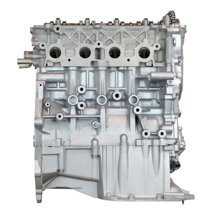
- This engine was introduced in 1999 and has won several awards since, including a series of International Engine of the Year awards from 2000 onwards. The 1NZ-FXE appears in the Prius and Prius c. The 1NZ-FE is the low-compression, 1.5-liter Otto cycle variant of the 1NZ-FXE with 107 horsepower and 103 lb.
- Manuals UD Workshop Manuals Free Online Service and Repair Manuals for All Models Corona L4-2366cc 22R (1982) Echo L4-1.5L (1NZ-FE) (2000).


Toyota Repair manuals English 9.9 MB 1NZ-FE ENGINE. EM 8 1NZ FE ENGINE MECHANICAL DRIVE BELT INSTALLATION 1. INSTALL VANE PUMP V BELT a Temporarily install the belt on each pulley. Engines Toyota 1NZ-FE, 2NZ-FE manual repair, maintenance and operation download.
1nz Fxe Engine

Toyota 1nz Fxe Engine Manual Pdf
EM 8 1NZ FE ENGINE MECHANICAL DRIVE BELT INSTALLATION 1. INSTALL VANE PUMP V BELT a Temporarily install the belt on each pulley. 2. INSTALL GENERATOR V BELT a Temporarily install the belt on each pulley. INCORRECT 3. ADJUST GENERATOR V BELT a Insert the adjusting bar between the engine RH mount bracket and generator. Push the bar towards the vehicle front to adjust the belt tension. CORRECT NOTICE Do not insert the bar between the oil control valve and generator. It could damage the oil Adjusting Bar Generator control valve. EM Vehicle Front A077960E03 b First tighten bolt A, and then tighten bolt B. Bolt A Torque 18.5 N m 189 kgf cm, 14 ft. lbf for bolt A 54 N m 550 kgf cm, 40 ft. lbf for bolt B 4. ADJUST VANE PUMP V BELT Bolt B a Using the bar, adjust the belt tension. A050691E01 b First tighten bolt B, and then tighten bolt A. Torque 44 N m 449 kgf cm, 33 ft. lbf Bolt A 5. CHECK DRIVE BELT TENSION See page EM 6 6. INSTALL ENGINE UNDER COVER RH Bolt B A050692E01 1NZ FE ENGINE MECHANICAL TIMING CHAIN EM 25 REMOVAL 1. DISCONNECT CABLE FROM NEGATIVE BATTERY TERMINAL CAUTION Wait at least 90 seconds after disconnecting the cable from the negative battery terminal to prevent airbag and seat belt pretensioner activation. 2. REMOVE FRONT WHEEL RH 3. REMOVE NO. 2 CYLINDER HEAD COVER a Remove the 4 nuts and No. 2 cylinder head cover. EM A066316E01 4. REMOVE IGNITION COIL a Remove the 4 bolts and pull out the 4 ignition coils. A079683E01 5. REMOVE VENTILATION HOSE a Disconnect the ventilation hose from the cylinder head cover. A080969E01 6. REMOVE NO. 2 VENTILATION HOSE a Disconnect the No. 2 ventilation hose from the cylinder head cover. A080970E01 EM 26 1NZ FE ENGINE MECHANICAL TIMING CHAIN 7. REMOVE CYLINDER HEAD COVER a Remove the 9 bolts, 2 nuts and cylinder head cover. 8. REMOVE GENERATOR V BELT See page EM 7 9. REMOVE GENERATOR See page CH